PC Engines APU2
This page describes how to run coreboot on PC Engines APU2 platform.
Technology
CPU |
AMD G series GX-412TC |
CPU core |
1 GHz quad Puma core with 64 bit support 32K data + 32K instruction cache per core, shared 2MB L2 cache |
DRAM |
2 or 4 GB DDR3-1333 DRAM |
Boot |
From SD card, USB, mSATA SSD, SATA |
Power |
6 to 12W of 12V power |
Firmware |
coreboot with support for iPXE and USB boot |
Required proprietary blobs
To build working coreboot image some blobs are needed.
Binary file |
Apply |
Required / Optional |
|---|---|---|
amdfw.rom* |
AMD Platform Security Processor |
Required |
AGESA.bin |
AGESA Platform Initialization |
Required |
xhci.bin |
AMD XHCI controller |
Optional |
(*) - package containing all required blobs for PSP. Directory, in which all blobs are listed and available is: 3rdparty/southbridge/amd/avalon/PSP
Flashing coreboot
Type |
Value |
|---|---|
Socketed flash |
no |
Model |
W25Q64 |
Size |
8 MiB |
Package |
SOIC-8 |
Write protection |
jumper on WP# pin* |
Dual BIOS feature |
no |
Internal flashing |
yes |
(*) - It is used in normal SPI mode, but can be dangerous when using Quad SPI Flash. Then, pull-down resistors should be considered rather than jumper.
Internal programming
The SPI flash can be accessed using flashrom.
flashrom -p internal -w coreboot.rom
External programming
IMPORTANT: When programming SPI flash, first you need to enter apu2 in S5 (Soft-off) power state. S5 state can be forced by shorting power button pin on J2 header.
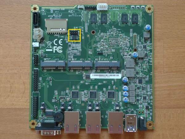
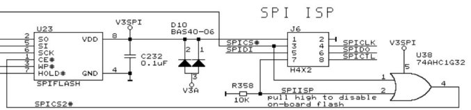
The external access to flash chip is available through standard SOP-8 clip or SOP-8 header next to the flash chip on the board. Notice that not all boards have a header soldered down originally. Hence, there could be an empty slot with 8 eyelets, so you can solder down a header on your own. The SPI flash chip and SPI header are marked in the picture below. Also there is SPI header and SPI flash pin layout included. Depend on using header or clip there are important rules:
using header J6 - don’t connect 1,7,8 pins
using clip U23 - don’t connect 3,7,8 pins
Also signatures at the schematic can be ambiguous:
J6 SPIDI = U23 SO = MISO
J6 SPIDO = U23 SI = MOSI
There is no restrictions as to the programmer device. It is only recommended to flash firmware without supplying power. External programming can be performed, for example using OrangePi and Armbian. You can exploit linux_spi driver which provides communication with SPI devices. Example command to program SPI flash with OrangePi using linux_spi:
flashrom -f -w coreboot.rom -p linux_spi:dev=/dev/spidev1.0,spispeed=16000
apu2 platform with marked in SPI header and SPI flash chip
SPI header pin layout
Schematics
PC Engines APU2 platform schematics are available for free on PC Engines official site. Both configurations (2GB/4GB) have the same PCB and schematic.