MSI MS-7D98
This page describes how to run coreboot on the MSI MS-7D98.
Model naming scheme, memory types
This port was developed and tested on an MSI PRO B760-P WIFI DDR4.
However, maintainer of this board belives it also covers other MS-7D98 models.
While only DDR4 memory’s been tested at this moment, adding support for DDR5 models should
be trivial.
Most likely the only required change is changing MEM_TYPE_DDR4 to
MEM_TYPE_DDR5 in romstage_fsp_params.c
Marketing name |
Memory type |
Status |
|---|---|---|
PRO B760-P WIFI |
DDR4 |
Supported, fully functional |
B760 GAMING PLUS WIFI |
DDR4 |
Untested, likely functional |
PRO B760-P WIFI |
DDR5 |
Untested, currently unsupported |
B760 GAMING PLUS WIFI |
DDR5 |
Untested, currently unsupported |
PRO B760-VC WIFI |
DDR5 |
Untested, currently unsupported |
Required proprietary blobs
To build full working image of coreboot, the following blobs are required:
Binary file |
Apply |
Required / Optional |
|---|---|---|
FSP-M & FSP-S |
Intel Firmware Support Package |
Required |
Microcode |
CPU Microcode Update |
Optional (recommended) |
ME |
Intel Management Engine |
Optional |
FD |
Intel Flash Descriptor |
Optional |
VBT |
Intel Video Bios Tables |
Optional (iGPU) |
Gen5.bin |
Synopsys PCIe Gen5 firmware |
Required (if ME off) |
RaptorLake-S FSP (pulled automatically from 3rdparty/fsp submodule) works perfectly with
all CPU families (AlderLake, RaptorLake) supported by LGA1700 socket.
Including microcode updates is highly recommended for RaptorLake (13/14th Gen) CPUs,
as microcodes released before August 2024 will cause silicon degradation over time
(first fixed version: 0x129).
Vendor of this board provides full UEFI firmware images available to download for respective models, which include IFD and ME regions.
It’s highly recommended to update them while flashing coreboot, especially if you’ve decided to disable ME by setting HAP bit within IFD.
If you’ve decided to disable Management Engine by setting HAP (High-Assurance Profile) bit within the Flash Descriptor, you need to:
Open stock firmware in tool such as UEFITool and extract the file called:
CPD_partition_Code_gen5.bin.Include it in your build:
Chipset -> Include PCIe 5.0 HSPHY firmware in flash.
This file contains firmware for Synopsys PCIe 5.0. If this file is missing and HAP bit is
set, PCIE_E1 slot will not work.
Flashing coreboot
It’s impossible to flash coreboot internally due to flash protection being active, first flash has to be done with an external programmer.
TPM header (JTPM1) can be re-purposed to create a flashing cable which will leave no
marks on the board, leaving warranty intact. Be aware that the header uses 2.0mm pitch
(as opposed to “regular” 2.5mm pitch in standard dupont wires).
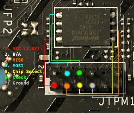
SPI chip is a Winbond 25Q256JWFQ and uses 1.8V logic.
Please make sure to use a 1.8V-capable flasher
(such as Glasgow Interface Explorer or Tigard) or level-shifter with 3.3V flasher
(such as CH347).
If you’ve decided to flash coreboot without touching HAP bit, IFD or ME, it can be done with the following command:
flashprog -p [programmer] --ifd -i BIOS -w build/coreboot.rom
However, if you’re updating your IFD and ME regions, the entire SPI flash needs to be overwritten:
flashprog -p [programmer] -w build/coreboot.rom
For debugging purposes, standard RS232 header (JCOM1) is available.
Tested and working
All PCIe/M.2 ports
All RAM slots
All SATA ports (4x SATA, AHCI drives in M2_2 socket under PCH)
All USB ports
Both iGPU outputs, as well as 3D acceleration in OS
Built-in audio (ALC897), including jack detection
Built-in CNVi AX211 WiFi/BT
Built-in RGB controller (“MSI MYSTIC LIGHT”, using OpenRGB in Linux)
Built-in Realtek RTL8125 2.5GbE LAN
Disabling Management Engine by setting HAP bit in IFD
DRAM_LED during memory training (romstage) for easier debugging
SuperIO (RS232, PS/2, FAN control, Voltage/Temperature reporting)
PC Speaker (goes beep-boop)
OS: Gentoo Linux (kernel 7.2.9), Windows (10/11)
Payloads: EDK2, LinuxBoot
IOMMU/VT-x (PCIe passthrough)
PCIe ReBAR (Resizable BAR)
Power on/off, suspend/resume (S3), hibernate
Notes
Payload and pre-OS display output:
If you are using an external graphics card (AMD, Nvidia, Intel Arc), you will see output in your OS as soon as kernel initializes the card (called “modesetting” in Linux) regardless of payload you chose.
If you’re planning to primarly use an external card and require a video output during firmware phase, you must use EDK2 payload and include the
PciPlatformDxedriver (which loads GOP drivers from PCIe devices) by enabling:Payload -> Load and Execute OpROMs on PCIe devicesPlease note that if you are using an Intel Alchemist or Battlemage card, enabling:
Devices -> Extend resource window for PCIe devices above 4Gis mandatory.Power management: According to reverse-engineering done by creator of the port, ASPM on this board doesn’t work (even on stock firmware), as (almost) all PCIe slots share a single reset line. PCH RootPort 5 (PCIE_E3) is an exception to this rule, where vendor had to implement proper power management to sell expensive Thunderbolt 4 cards of dubious usefulness.
Unimplemented functionality:
Thunderbolt card is expensive and unlikely to be paired with budget board (untested)
Some SuperIO sensors don’t report values (CPU 1P8, CPU VDDP, AVSB, VBat)
Specification
CPU socket |
Intel LGA1700 (ADL/RPL) |
PCH |
Intel B760 |
Super I/O |
Nuvoton NCT6687D |
SPI |
Winbond 25Q256JW 32MiB 1.8V |
NIC |
Realtek RTL8125 |
Audio |
Realtek ALC897 |