Framework Laptop 13 AMD Ryzen 7040 Series (Azalea)
Notice
This firmware is not production quality, and is being developed only as a proof-of-concept. AMD’s FSP and openSIL firmwares for the Phoenix SoC are not fully featured. It is recommended that you do not replace the OEM Firmware on your Azalea board if you are using it as a daily-driver laptop.
Most notably, suspend is not supported in this firmware. You should in theory still be able to use hibernate from the OS, but S3 and S0i3 are not being developed or tested.
Azalea Platform Specs
CPU
AMD Ryzen 5 7640U (4.9GHz, 6-cores) or
AMD Ryzen 7 7840U (5.1Ghz, 8 cores)
Memory
2 DDR5 SO-DIMM slots - Each accepting 32GiB DDR5-5600 SO-DIMMs
Storage
2280 M.2 M-Key slot - 1 NVMe M.2 SSD
WIFI/BT:
2230 M.2 E-Key slot
Comes with AMD RZ616 Wi-Fi 6E / BT 5.2
Intel modules tend not to work
Battery
Compatible with: 55Wh, 61Wh, 74Wh
Ports
4 expansion slots
Audio
Realtek ALC295 Codec
3.5mm combo headphone jack
EC
Nuvoton NPCX993
Mainboard
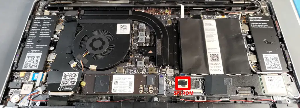
Notice that the SPI ROM here is socketed. For mass-production devices, it’s soldered down.
Flashing coreboot
Type |
Value |
|---|---|
Socketed flash |
no |
Vendor |
GigaDevice or Winbond |
Model |
25LR256EYIG or 25Q256JWEQ |
Size |
32 MiB |
Voltage |
1.8V |
In circuit flashing |
Yes, if header is populated |
Package |
WSON8 |
Write protection |
No |
Internal flashing |
Yes |
Update instructions
Warning
Before flashing, make sure you have a hardware flash tool to recover the system.
This procedure can render your laptop un-bootable until the ROM chip is updated.
The coreboot project assumes no liability for firmware that does not work as expected.
Flashing Notes
Before starting, please look over the Flashing firmware tutorial and make a backup of your ROM chip to recover if anything goes wrong.
The typical way to flash a chip still attached to a board is to use a test clip of some sort which allows you to connect an external programmer to the pins of the SPI ROM or pads on the mainboard. These can be found for sale in various places by searching for “WSON8 test clip”. An SOIC8 test clip (commonly referred to generically as “pomona clips”) may work as well.
There are a number of hardware flash tools which can be used. Make sure you pick a programmer that supports 1.8V flashing. You can damage your board by flashing at 3.3V or 5V. Professional developers tend to use the Dediprog SF100, but that’s a very expensive tool for someone only doing this once.
Schematics and Pinout information
Partial Mainboard Schematic
A block diagram and partial mainboard schematic has been released by Framework Computer Inc under the CC By 4.0 license. The schematic is available on their github site.